
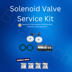
Breville solenoid service guide
Replace the plunger, clean the valve and refit the solenoid step by step.
For Breville BES900, BES920, BES980 and BES990 machines using the OLAB Solenoid Valve Service Kit.
Common reasons for this repair
- Buzzing or humming during a shot
- Low or inconsistent water flow
- A stuck or leaking solenoid
At a glance
Allow about 30–45 minutes. This guide involves opening the machine, disconnecting mains wiring and handling small valve parts.
Before you start
- Switch the machine off, unplug it from the wall and let it cool completely.
- Photograph every connection before removing it. Reconnect each terminal, including the green/yellow earth lead, to its original position.
- Keep water and descaler away from the coil, terminals and wiring. Never restore power while the cover is off.
- If you are not confident working around mains wiring, use a qualified technician.
Tools and supplies
- Phillips screwdriver and T20 Torx driver
- Deep 17 mm socket; impact driver if available
- Large adjustable wrench or bench vice, 13 mm spanner and pliers
- Wire brush and suitable descaler
- New zip tie, clean water and the service kit
- Optional: coffee-cleaning tablet for oily metal parts
Select any photo to see it at full size.
1. Open the machine
Work on a cool, unplugged machine.
-
Remove the front screws
Remove the two Phillips screws underneath the front panel. 
-
Remove the rear screws
Remove the two T20 Torx screws at the back of the machine. 
-
Lift the top cover
Carefully lift the top cover to expose the solenoid. Keep the screws together for reassembly.


2. Disconnect and remove the valve
Document the wiring before touching any terminal.
-
Record the wiring and remove the purge hose
Photograph and label every terminal in place. Cut the old zip tie, then gently lift the purge hose off its fitting. 
Pull connectors by their insulated bodies, never by the wires.
-
Release the locking connector
Press the catch on the lower locking connector and pull the connector straight off by its body. 
Keep track of the green/yellow earth lead so it can be returned to its original connection.
-
Remove the coil and valve body
Undo the top retaining nut and lift off the coil.
Loosen and remove the four numbered solenoid mounting screws gently. 
Take care: These screws can snap. If one is seized, apply WD-40 at its thread and let it penetrate; do not force it. Keep spray off the valve water path, seals, coil and wiring; wipe away residue before reassembly.
Once the four screws are out, lift the assembly free and set it on a clean work surface. Keep loose parts together.


3. Clean and replace the plunger
Keep the electrical coil and wiring dry throughout cleaning.
-
Descale the exposed plate
Brush suitable descaler onto the scaled metal surfaces of the exposed solenoid mounting plate. 
Follow the descaler's label. Keep liquid away from the coil, terminals and wiring.
-
Remove the old seals and pins
Lift the old seals and pins out of the detached solenoid plate. Set them aside in removal order. 
-
Open the solenoid body
Hold the body securely with a large adjustable wrench or in a vice, and use a deep 17 mm socket with an impact driver, if you have one, to open it. 
Use the impact driver to open the body; tighten the body gently when reassembling.
-
Take out the old plunger
Remove the old plunger from the opened solenoid body and note its orientation. 
-
Clean coffee oil residue if presentOptional
If the metal parts have coffee oil residue, soak them in hot water with a coffee-cleaning tablet, then rinse them thoroughly with clean water. 
Soak metal valve parts only. Do not immerse the coil or any electrical part; dry the cleaned parts before reassembly.
-
Clean the mounting surface
Brush away any remaining scale from the solenoid mounting plate inside the machine and remove the loosened residue. 
-
Fit the replacement plunger
Check the spring and green sealing face on the kit plunger, then fit it into the body in the original orientation. 


4. Reassemble and test
Restore every part and connection before applying power.
-
Rebuild and refit the valve
Return the pins to their original positions.
Seat the seals, align the solenoid plate and valve body, then tighten the four mounting screws evenly and gently. 
Refit the coil and retaining nut without over-tightening. Do not guess a torque setting.
-
Reconnect the hose and every terminal
Push the purge hose fully onto its fitting and secure it with a new zip tie. Reconnect each terminal exactly as photographed or labelled, including the green/yellow earth lead.
Take care: If a connector's original position is uncertain, stop and get a qualified technician to check it.
-
Close the machine before testing
Refit the top cover and all front and rear screws. Only then reconnect power and run a normal check for flow and external leaks.
If the machine leaks, sounds abnormal, or shows an electrical fault, switch it off, unplug it and seek service.

If a mounting screw breaks
Stop loosening the other screws if a fastener begins to twist or snap. Work only with the machine unplugged. Keep WD-40 off the valve water path, seals, coil and wiring; wipe away residue before reassembly.


If the screw is flush or will not turn, a technician may need to cut a slot or drill and re-tap it. Avoid damaging the valve's sealing surface.
Final check
- The plunger, spring, pins and seals are seated in their original positions.
- The valve body, coil, hose and new zip tie are secure.
- Every terminal, including the earth lead, is back where it was photographed.
- The top cover and all screws are fitted before the machine is plugged in.
- After a normal test, flow is consistent and there are no external leaks or unusual sounds.
DIY repairs carry risk. If anything is uncertain, stop and consult a qualified technician. Read our full disclaimer.